|
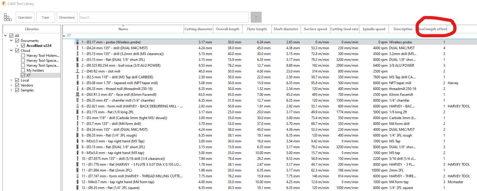
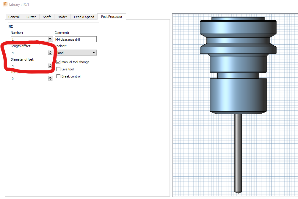
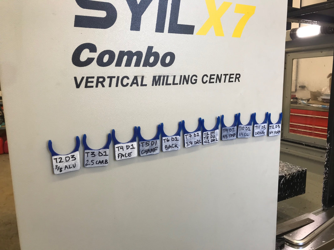
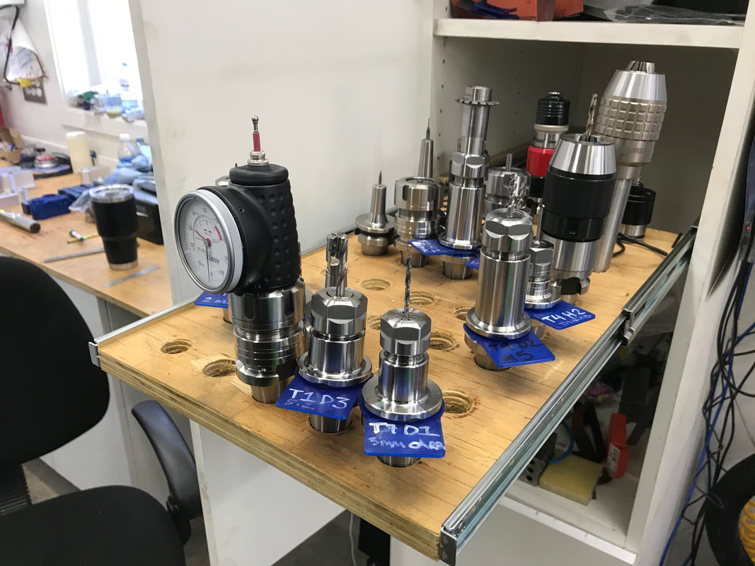
The generic Siemens 840D post has some incompatibilities with the Syi X7. One of them is proper handling of D numbers (tool "edges"). Tool edges allow you to assign multiple tools to a given tool base number. So you can have T12D1 for a 3mm drill, and T12D2 for a 1/4" rougher. There are obvious risks with this system but for me the benefits outweigh them. This way when you set up for a job you do not need to measure the tools again. Here is my fusion library: The post processor will need to be edited as well. Open it in a text editor, I suggest Microsoft visual studio code (free). Find this line: Comment that line out by putting "//" in front of it (so you can keep it for reference) like this: // var lengthOffset = 1; // optional, use tool.lengthOffset instead and paste this line below it: In theory this should be all you have to do, but this causes the 808D to alarm when you call a NEW tool number, and the D number is not 1. In order to make this work I found you need to change the actual tool change code to send the D number after the M6 call. Find this code in the post processor, and comment it out as shown using the "/*" above and the "*/" below: Then paste this code below the code above: UPDATE: You also need to change this in another area of the post, that handles if you change WCS in the program (like two parts in different vices and each has their own WCS (G54.. G55 etc.). This was found in the "// WCS" area of the post, about line 1328. It is a good idea to leave the old code just in case. The /* and */ make what is in between not process (commented out). Change it to this: 'Now in the control you can add additional "Edges" in the tool offset table by hovering over the desired tool number then pressing the "edges" key, then "new edge" and enter in the length offset, and diameter (optional). I am using 3D printed tool tags (print in PETG so they aren't too brittle) to keep control of what tools are loaded in the machine:
1 Comment
I just switched my machine over to the latest head version so I decided to document it as a bit of an assembly guide. Hope you find it helpful!
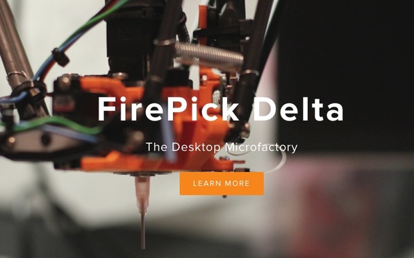
Update! 2016-04-28: The head is built and everything went smoothly. The pick and place isn't running yet as I had to order a new smoothie board to run it. Hopefully it will be testing in the next 2 weeks.
We have created a port expander for the RFduino, with the eventual goal of adding 8 more I/O's to the RFduino. We selected the MCP23008 because Adafruit has an Arduino library for it, but it turns out that the library isn't directly comparable with RFduino. I am sure the changes required are minor but I decided to do a simple tutorial on writing to this port expander directly!
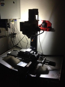 I decided to go ahead and install limit switches so I could do the TTS repeatable tool holders, probe and MSS (Mach Standard Mill) implementations at once. I am very sick of touching off after every tool change!! It was Taking me forever to come up with a design that I could machine on the mill, and then it hit me, 3D print them! I have make simple mounts for the TEMCO limit switches found here. X axis mount: This was the easiest because the adjustable stops were already on the cross slide. I also extended the bottom so that it would protect the Y axis lead screw that gets exposed. This is a brief overview of the OTA (Over The Air) firmware updating procedure for BLE112 or BLE113 systems equipped with the required hardware for OTA updates (like our BLE113 breakout board). This procedure (and our BLE113 breakout board) strictly follows Bluegigas APP NOTE for OTA updating.
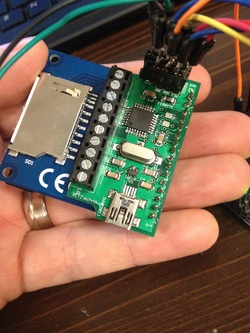 This is my custom board incorporating an ATMEGA 328p MCU, lipo battery charger with USB connector for charger powering, 8MHz crystal oscillator, lipo battery powered, SPI programming header and header for a 1.8" SPI TFT display. The device is for my "Bubba Keg", a creation made for a few friends. Essentially it is a control system for the 70oz Bubba Keg insulated mugs. It uses an ultrasonic sensor in the lid to determine quantity and a PTC thermistor in the cup to determine content temperature. For the old design I used a custom PCB that joined an Arduino Nano and 1.8" TFT display. It ran off a 9v battery and was housed in a generic enclosure. it was far more bulky than I wanted it to be. That is why I went for a SoC solution. The display has gauges for quantity, temperature and voltage. The display also shows you calculated L/Hr consumption rate and time to empty. Programming the ATMEGA without USB support was the challenge, but I found some tutorials on using another arduino (UNO) as an ISP (In Service Programmer). I wired the two together and used the Arduino IDE to program the chip. I was very pleased to see it working! Not having the bootloader on the chip means it starts up lightning fast and has more room for programming space. I chose 8MHz to conserve power as it was more important than performance. Next step will be to custom design and 3D print a nice compact enclosure for it and test fit it on a mug! 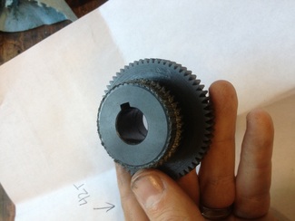 Seems I wasn't immune to having the plastic high/ low speed gear (p/n P0704212) strip on me. I crashed the mill in low gear cutting steel. It was hard enough to rotate the head about 20 degrees. Grizzly was good enough about supplying me one under warranty and I purchased an extra one for good measure. I believe I know a contributing factor to the gears stripping at least slightly before they should. I initially chalked it up to poor rigging as the low gear did not engage 100% of its tooth width. The more I looked at it however I realized there is no possible way to adjust the gear mesh quality and it does not engage 100% in low or high gear. 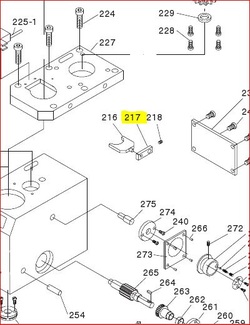 A possible solution would be to re manufacture the arm of the high/ low speed fork arm. If you were to make the fork arm p/n P0704217 a little longer than it currently is it would allow you to have more throw on either end of the travel, allowing the gears to mesh completely. Another option would be to make another detent plate (item 273 on the left) with the detents located further apart. I am not sure if something else limits the throw of the knob but I do not remember being able to rotate it past the detents. 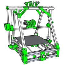 Since I already have the CNC mill (G0704) in the shop, the next logical choice was a 3D printer. I wanted something relatively affordable yet capable. I went with a MendelMax 1.5 Deluxe kit from 3D Factory LLC. My free time is limited but I felt the value of having built it from scratch was worth the extra time vs. buying assembled. I am already well versed in Arduino and CNC in general so I feel I am at an advantage to most, time will tell! |
Author
Peter Betz Archives
April 2020
Categories
All
|
Prices in US Dollars



 RSS Feed
