 I just switched my machine over to the latest head version so I decided to document it as a bit of an assembly guide. Hope you find it helpful! EXPLODED DRAWING:
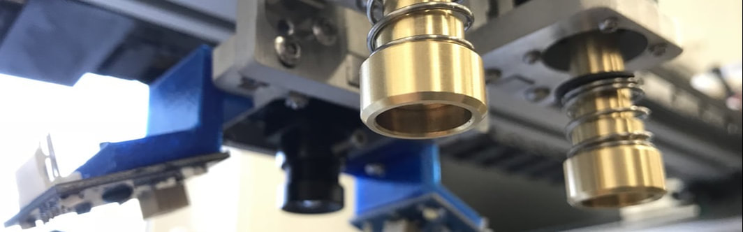
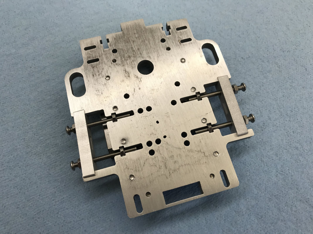
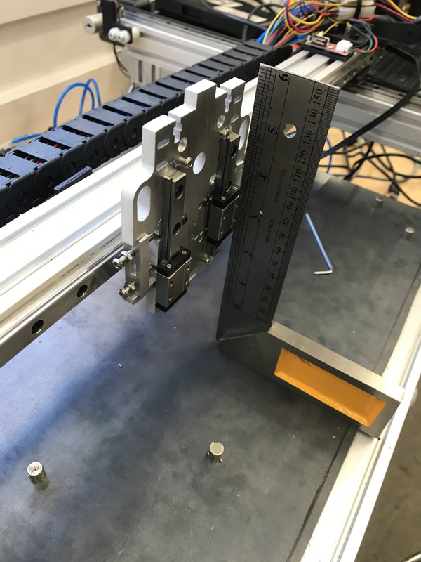
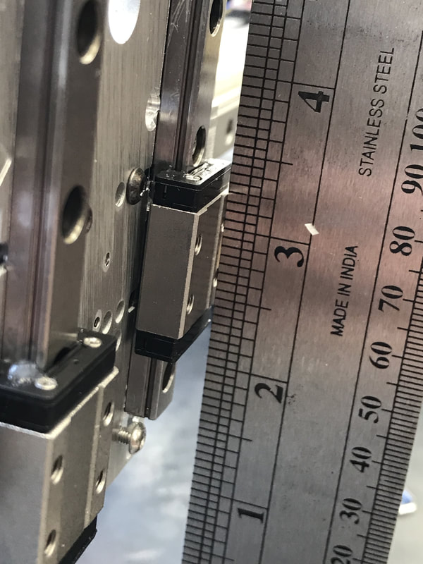
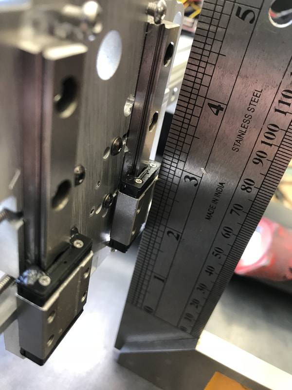
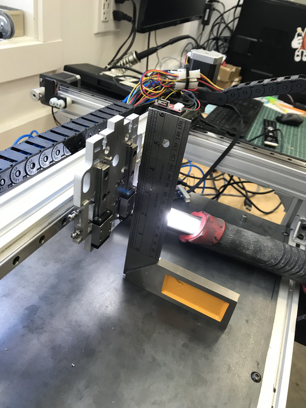
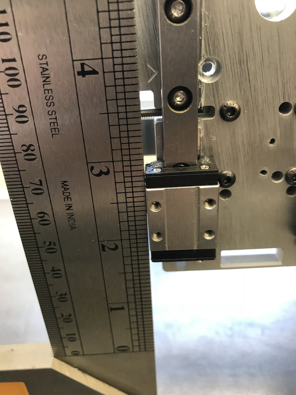
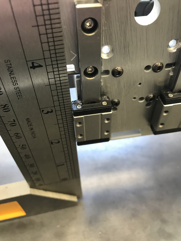
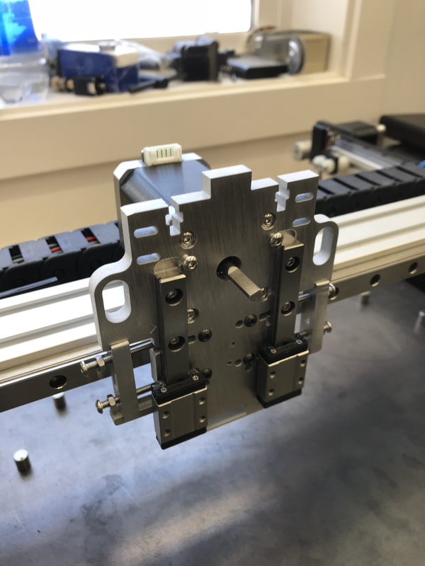
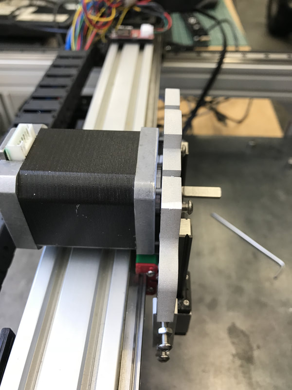
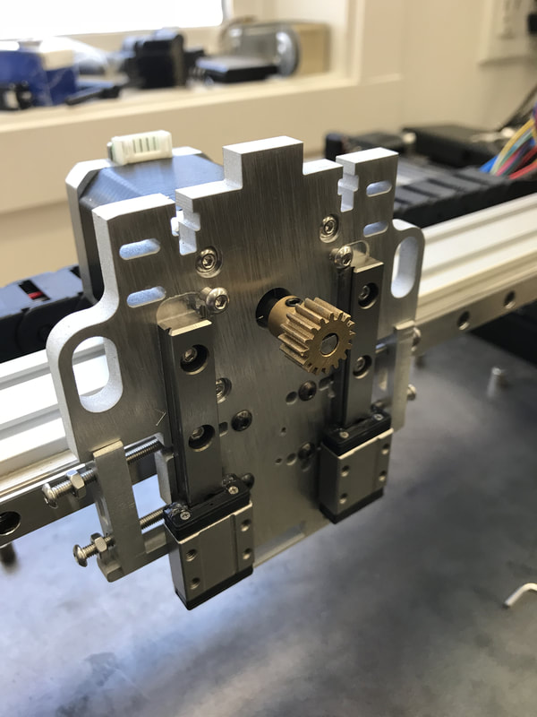
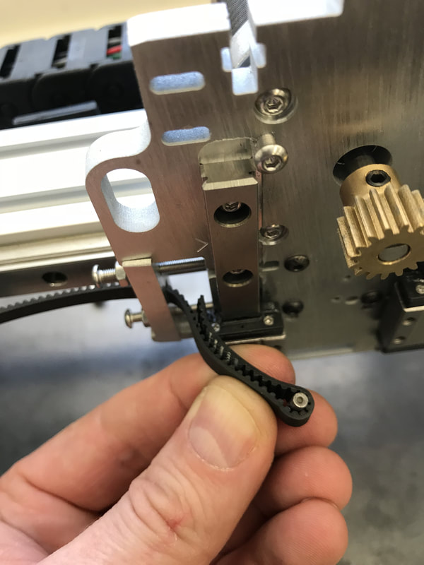
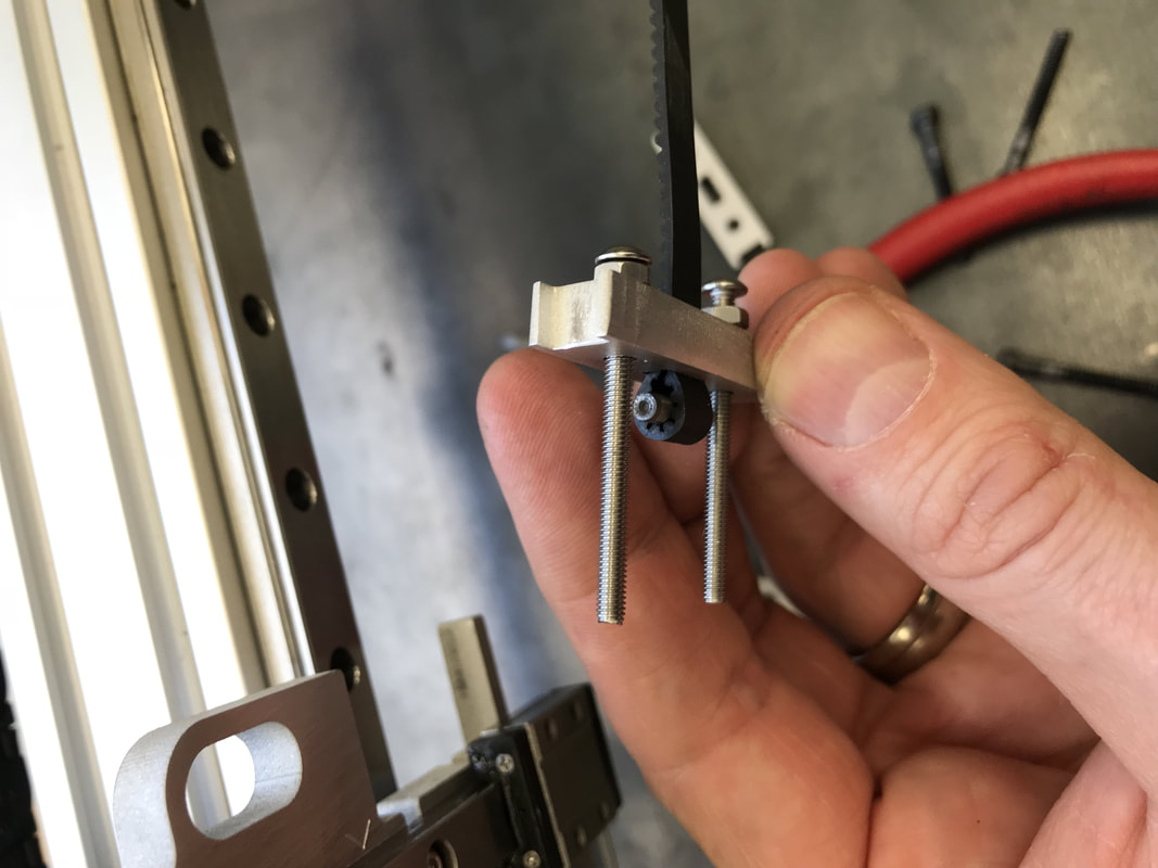
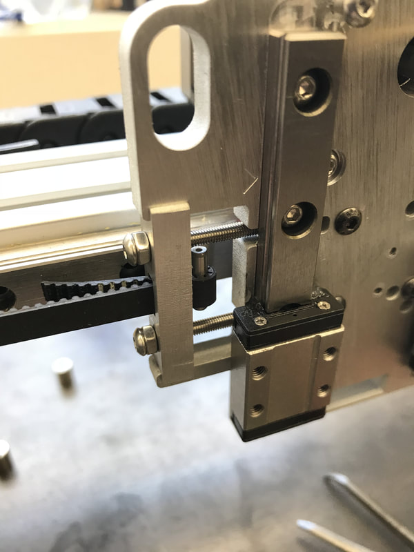
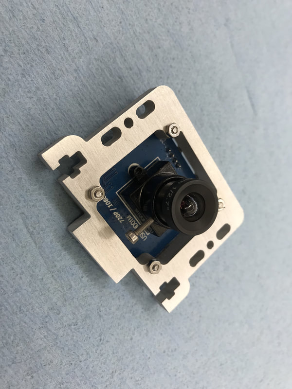
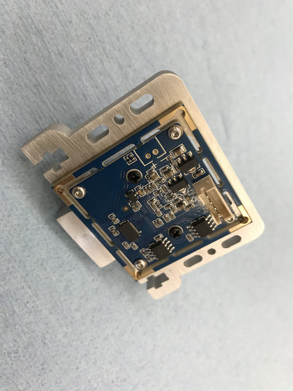
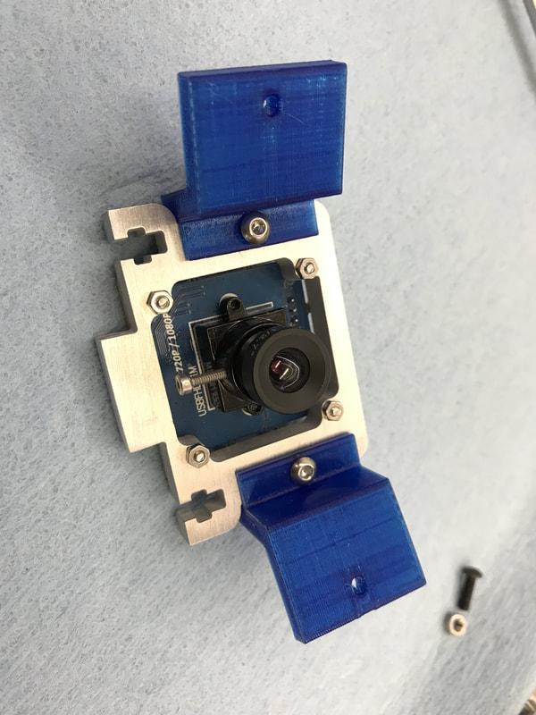
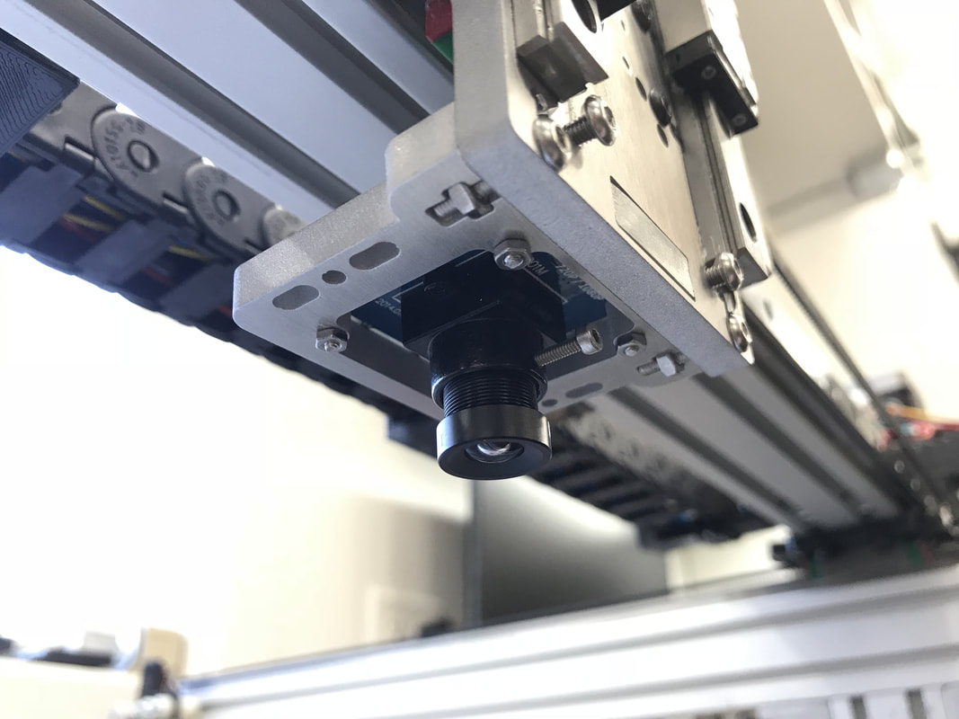
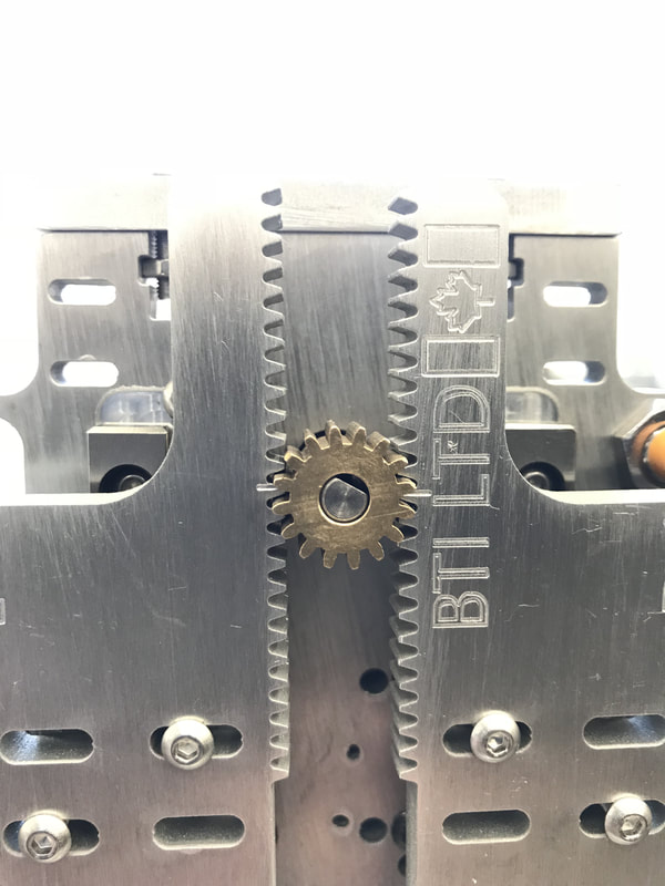
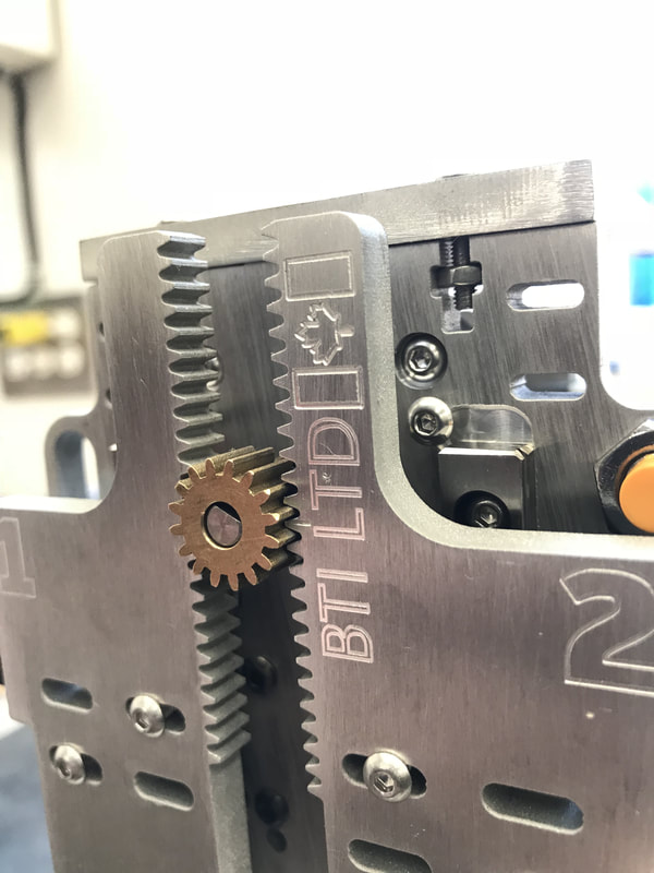
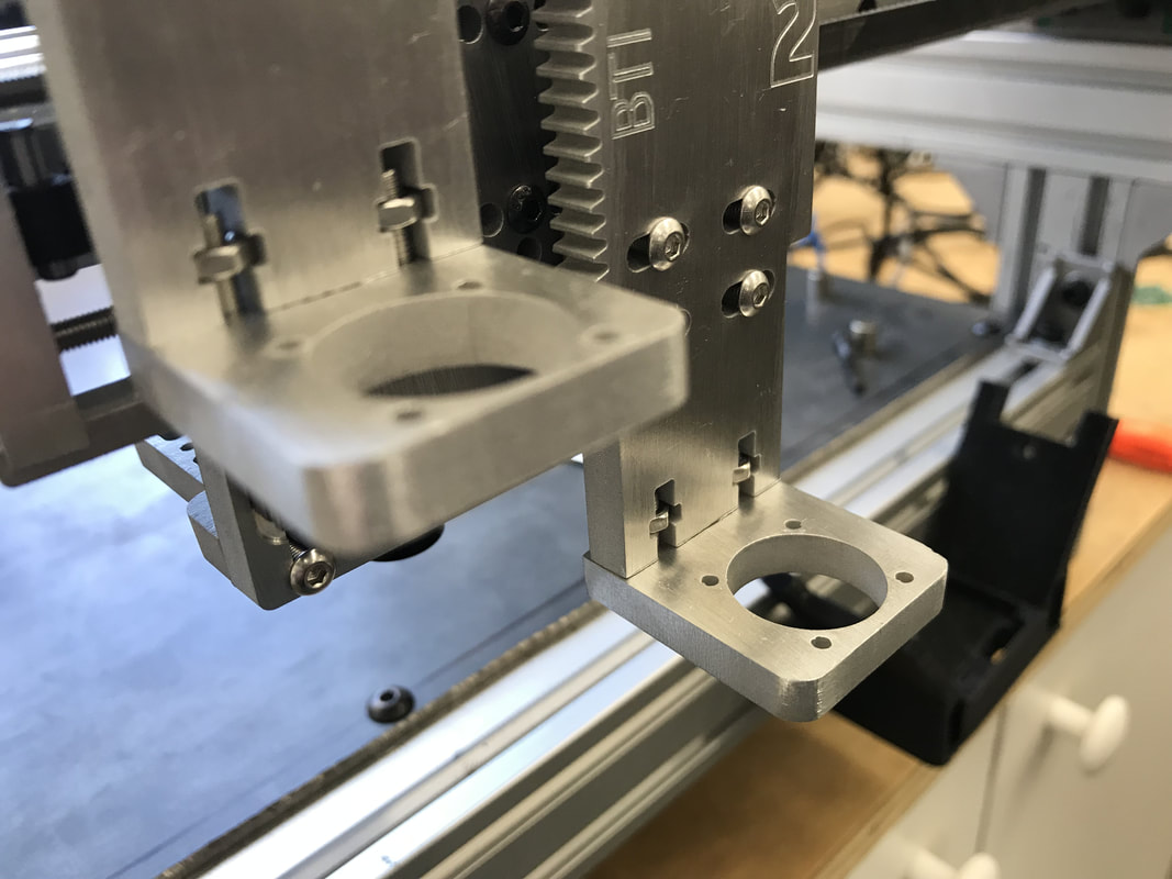
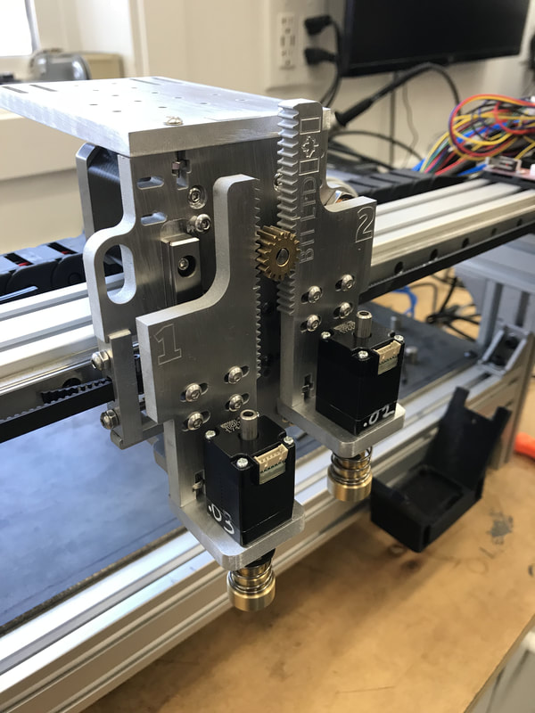
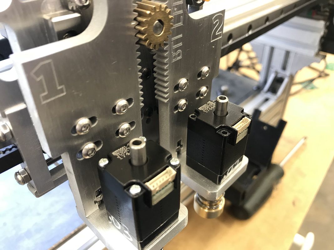
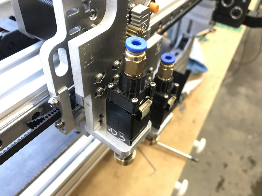
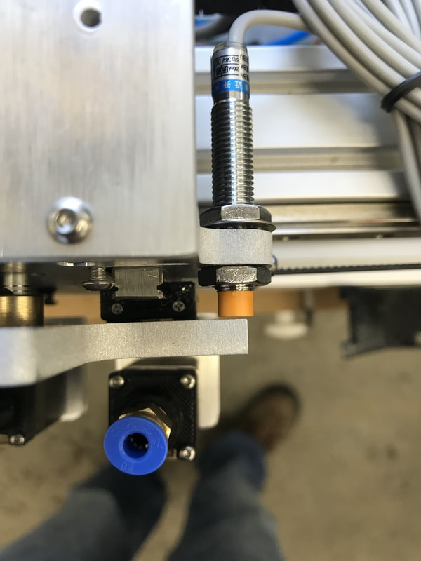
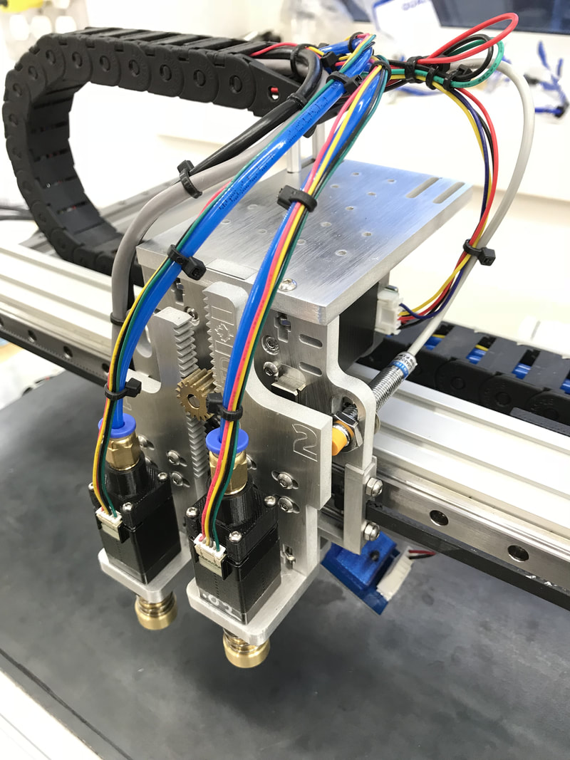
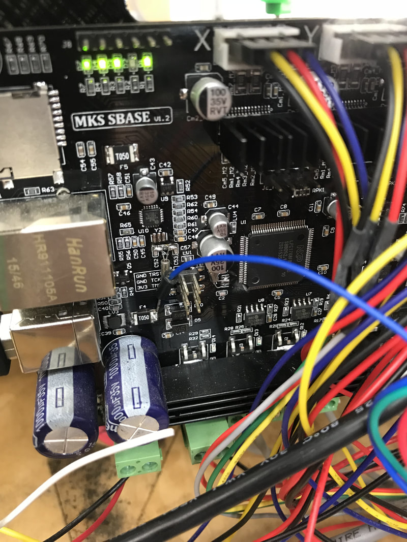
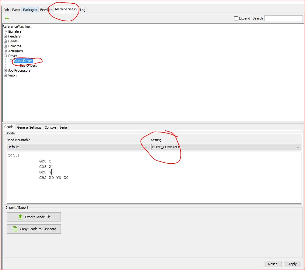
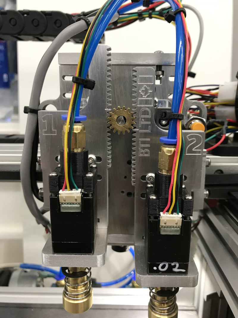
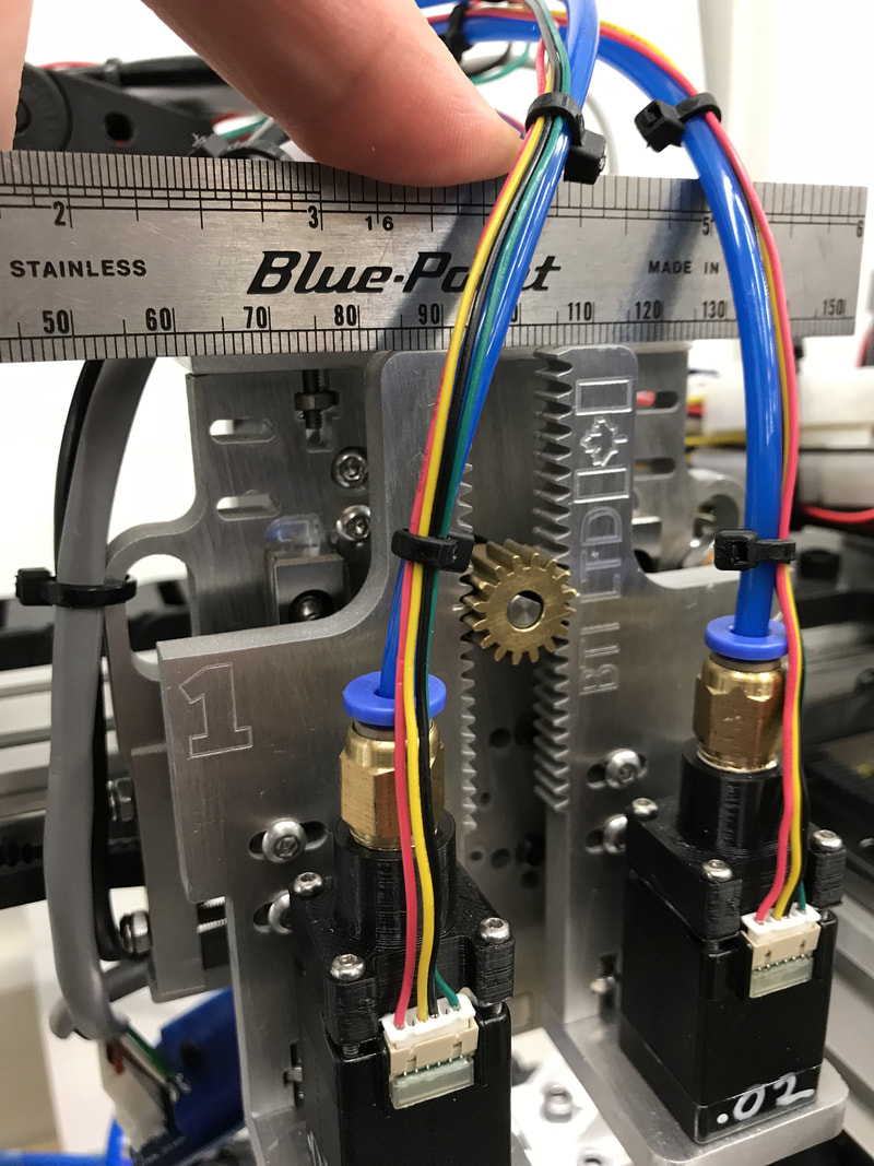
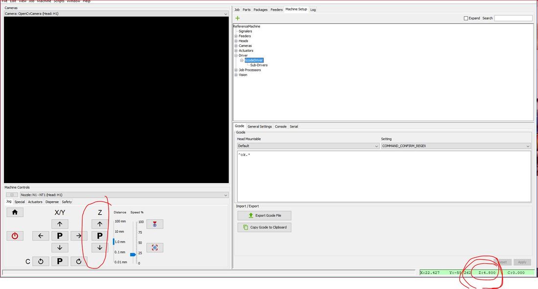
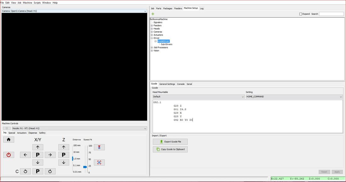
STEP 1: Install the tensioner blocks on the main plate using 4 M3x35 screws, and 8 M3 nuts as seen below. The tensioner blocks fit a little snug so you may need to press them in. I agree that the screws are a little long.... STEP 2: Install the main head plate on the X axis bearing block using 4 M3x10 screws. This is the best time to align the head. Since I used a dial indicator attached to the X bearing block to level the bed, I simply used a machinist square to level the head front to back. I used shim stock between the X axis bearing block and the head plate. To align the head left to right, simply loosen the mounting screws to rotate the assembly around the Y axis. Since we machine a reference edge for the Z rails to square up against, you only need to perform this on one side. Take your time to align the head properly. STEP 3: Install the NEMA 17 Z stepper with 4 M3x10 screws. Align the motor so the connector is easily accessible (unlike in these pictures). Tighten the screws in an alternating pattern to ensure the motor sits flush on its small round boss (this will make sense when you go to install the motor). Install the spur gear. STEP 4: Connect belts (if you are using belts). You will need the supplied two little delrin pins to wrap the belt around. STEP 5: Install the proximity sensor. Only use one lock washer, on the back side of the head plate. Leave the sensor retracted as far as possible until the head is fully assembled. STEP 6: Install your ELP camera in the camera mount (ELP camera is not supplied, nor is the M2x10 mounting hardware). If you purchased or printed our 3D printed light panel mounts, now is the time to mount them as well using 2 M3 screws. Install the camera mount to the main head plate using 2 M3x14 screws and nuts. STEP 7: Install the top plate using 2 M3x14 screws and nuts. STEP 8: Install the left and right carriages using 8 M3x8 screws. Note the machined alignment marks that line up with the spur gear. Important note, run the carriage up and down to adjust the mesh on the gear. Find a good balance between low friction and excessive play. YOU WILL HAVE A SMALL AMOUNT OF PLAY BETWEEN THE GEAR AND RACK (WHICH RESULTS IN PLAY IN THE Z AXIS). THIS IS PERFECTLY NORMAL AND WILL NOT AFFECT PRECISION OR ACCURACY, ESPECIALLY WHEN USING SPRING LOADED JUKI NOZZLES. STEP 9: Admire engraving. STEP 10: Install the NEMA 8 motor mounts using 4 M3x14 screws and nuts. Align with carriages. STEP 11: Install NEMA 8 motors using 8 M2x8 screws. Do not over tighten and strip the heads. [If you purchased or printed our vacuum adapters, install them now. Remove the 8 phillips head screws that hold the motors together. Optionally, apply a thin film of sealant on the face of the adapter. Use the supplied 8 M2x35 screws to install. Do not apply excessive sealant as it may bind the motor shaft.] STEP 12: Adjust proximity sensor. Try to get the gap to 1mm or below. STEP 13: Wire and plumb. Inductive sensor connections: Connect the sensor to Z max end stop connections. Wire as per label on sensor (Brown +5v, Blue GND, Black signal). The sensor requires 5v or just below. On my MKS SBASE board the endstop voltages were too low (4.7v), I found a good 5v source on a fuse (F4) near the usb connector: STEP 14: To use our head you need the -edge branch of the smoothie firmware. [Please buy genuine smoothie boards (like the 5x), I didn't, I'm going to correct that mistake shortly]. This enables the unique homing method. Download the firmware.bin file from our product page here. Copy and paste the .bin file onto the smoothie SD card: 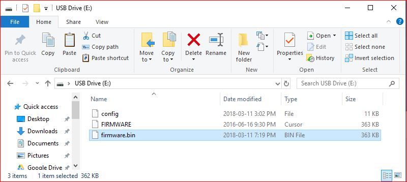 Reset smoothie. After reset the .bin file should have disappeared and a config and firmware file (type cursor) file remains: 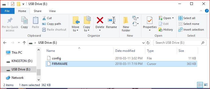 STEP 15: Copy and paste our example config from the product page here. Paste the example config file into the Smoothie SD card. It will ask you if you want to replace it, select yes. The config file is where you set a bunch of parameters, like steps per mm, homing, etc. You will definitely need to play inside this file, I suggest using a code editor like notepad++. STEP 16: Inside OpenPnP, click the "Machine Setup" tab, then expand "Driver", then click on the "GcodeDriver" heading. In the Setting drop down box, select "Home Command": Paste the following code in the box and click apply: Home the machine. You will notice that the head is not likely homed level: Use the machine controls to jog the head in Z, until the two carriages are level. I use a ruler across the top edges. Note the OpenPnP DRO reading (in this example, I jogged Z +4.8mm): Now modify the homing Gcode to move the Z axis the amount you measured with the DRO to balance the head, like this (then hit apply): Press the home button again, you should see that the head is now level and the Z DRO reads 0.00. STEP 17:
Revel in the fact that you just built a pick and place machine. THANK YOU FOR YOUR CONTINUED SUPPORT. SALES OF THESE TYPES OF PRODUCTS ALLOWS ME TO CONTINUE APPLYING TIME AND RESOURCES TO GIVE BACK TO THE AMAZING OpenPnP COMMUNITY!!!
1 Comment
|
Author
Peter Betz Archives
April 2020
Categories
All
|
||


 RSS Feed