|
We have created a port expander for the RFduino, with the eventual goal of adding 8 more I/O's to the RFduino. We selected the MCP23008 because Adafruit has an Arduino library for it, but it turns out that the library isn't directly comparable with RFduino. I am sure the changes required are minor but I decided to do a simple tutorial on writing to this port expander directly! Here is the code, but we will dissect it further: /* This code is written to test the BETZtechnik.ca RFduino port expansion shield. All three solder jumpers for address selection must be soldered so that the adress is compatable. Note that the board was supposed to create 8 additional I/0 pins, but do to some design errors the board in its current level supports 5 additional I/O's. This will be corrected in the next revision. This example code is in the public domain. */ #include <Wire.h> void setup() { Wire.beginOnPins(2, 3); Wire.beginTransmission(B0100111); // this is the adress of the chip Wire.write(0x00); // this is the mode for input/ output Wire.write(0x00); // this sets all ports to output Wire.endTransmission(); } void loop() { Wire.beginTransmission(B0100111); // address of chip Wire.write(0x09); // this is high/ low mode Wire.write(0xff); // this sets all pins to high (3.3v) Wire.endTransmission(); delay(2000); // 2 second delay Wire.beginTransmission(B0100111); Wire.write(0x09); // high/ low mode Wire.write(0x00); // set all ports low (0v) Wire.endTransmission(); delay(2000); //2 second delay } First thing first. i2c is handled by the "Wire" library, so be sure to include it in your sketch like you see at the start. RFduino expects you will be using it on other pins so we must define the pins that match the board itself, so instead of "Wire.begin()", we will use "Wire.beginOnPins(2, 3)". The first important step to communicate with the chip is to determine its address. You should close the three solder jumpers on the board to pull the chips A0, A1, and A2 high. Lets look at the data sheet: http://www.mouser.com/ds/2/268/21919e-53245.pdf 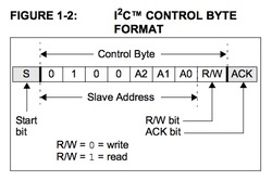 Here it shows the address selection. You can see the A0, A1, and A2 in the slave address (the chip is the slave). Since we closed the solder jumper, these are all now high. So the address is B0100111. If they were all low (which our board cannot reliably do at the moment since there are no pull down resistors) it would be B0100000. You can see in our code where we have indicated the address of B0100111. Now we need to look at setting the ports to input or output: 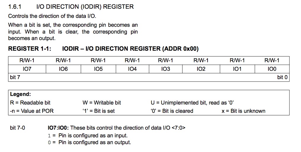 This table shows how you select as input (1) or output (0). This is all in binary, so if we wanted them all to be inputs, it would be 1111 1111 (this is represented in HEX for the code, so "0xff"), if they were all outputs it would be 0000 0000 (in HEX it is "0x00"). if you wanted only port IO0 to be input and the rest output it would be 0000 0001 (in HEX "0x01"). Each 1 or 0 represents each port, left to right, IO7 to IO0. Notice the "register" for this mode is (in bold, above the table) "0x00". So the code above directs the chip to set all ports to output (in setup if they are not going to change again) in this block: Wire.beginTransmission(B0100111); // this is the adress of the chip Wire.write(0x00); // this is the mode for input/ output Wire.write(0x00); // this sets all ports to output Wire.endTransmission(); Now we will look at setting the ports high or low: 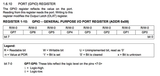 Here we see that the mode "register" is "0x09"
1 is high and 0 is low, so for all ports high it would be 1111 1111 (HEX is 0xff). For all ports low except port 6, it would be 0100 0000 (in HEX it would be 0x40). In our code we set all high by sending this string of commands to the chip (in the loop because we want it to switch back and forth): Wire.beginTransmission(B0100111); // address of chip Wire.write(0x09); // this is high/ low mode Wire.write(0xff); // this sets all pins to high (3.3v) Wire.endTransmission(); Then we set them all low using this: Wire.beginTransmission(B0100111); // address of chip Wire.write(0x09); // this is high/ low mode Wire.write(0x00); // this sets all pins to low (0v) Wire.endTransmission(); As you can see there are many, many more functions available in the chip such as interrupts and read capability, but I hope this proves to be a useful tool to help you dive in to this port expander!!
2 Comments
Leave a Reply. |
Author
Peter Betz Archives
April 2020
Categories
All
|
 RSS Feed