- Store
- >
- Machine tool accessories
- >
- Siemens 808D downloads
Siemens 808D downloads
SKU:
$0.00
Unavailable
per item
USE AT YOUR OWN RISK!
These macros are free to download. They have taken a tremendous amount of time to make. You may make a donation if you appreciate the work I have put in to this using the donations function: Donations
You can add this product to your cart and checkout (for 0$), then you will get a link to download the macros. Make sure your email address is correct so that I can send you important updates should any issues arise.
-
X7 808D post processor
-
Warm up program
-
Breakage detection
-
Auto tool length measuring
<
>
siemens-808d-TALBOT-EMVIO-BTI_v5.6(passThrough).cps
This post processor combines the work of Richard Talbot, George Konstantinidis and myself (Peter Betz). We are also working with Syil and Autodesk for an official post in the post library but that is taking some time to work out and test. Using an "unknown" post processor is risky, please try it carefully.
This post processor enables 4th axis (positional), D numbers, Cycle 832, safe tool change mode, spindle mode between tapped holes and move to position at end of program.
Use of D numbers is roughly covered in our blog post here (the post modifications described are already implemented in the post).
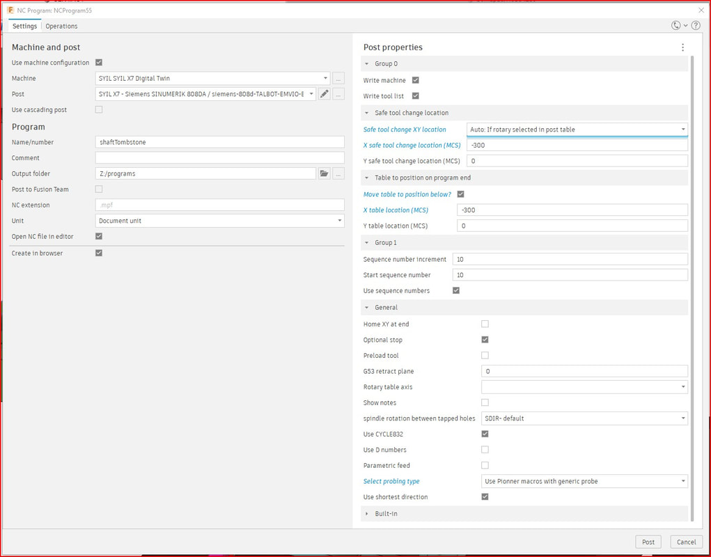
Safe tool change XY is useful if you have the 4th axis mounted, or some other large item on the table. It will move to the position set here prior to each tool change.
Cycle 832 will set the strategy (roughing, semi-finishing, finishing) based on the tolerance setting in the fusion 360 operation window.
Probing type. You can set it to either Pioneer probe installed, or use Pioneer macros with generic probe (like the Drewtronics wireless probe). The only difference with the two is whether or not the special Pioneer macros for turning the probe on and off are called. You can use these options to probe right from fusion 360! See our video here for a rough overview:
This video is probing with your machine table/ vise/ machine zero modeled in fusion 360. This method requires you keeping G59 all 0's to match the MCS coordinates:
Safe tool change XY is useful if you have the 4th axis mounted, or some other large item on the table. It will move to the position set here prior to each tool change.
- OFF: Disables move to safe tool change location
- ON: Always move to safe tool change
- AUTO based on 4th axis selected in post properties: Will move to safe location if there is a 4th axis selected in the post properties.
- AUTO based on whether 4th axis installed on the machine: This mode will check to see if there is a 4th axis enabled in the control (actual parameters in the control) and if there is one installed it will move to the safe tool change position.
Cycle 832 will set the strategy (roughing, semi-finishing, finishing) based on the tolerance setting in the fusion 360 operation window.
Probing type. You can set it to either Pioneer probe installed, or use Pioneer macros with generic probe (like the Drewtronics wireless probe). The only difference with the two is whether or not the special Pioneer macros for turning the probe on and off are called. You can use these options to probe right from fusion 360! See our video here for a rough overview:
This video is probing with your machine table/ vise/ machine zero modeled in fusion 360. This method requires you keeping G59 all 0's to match the MCS coordinates:
This video is probing from the target WCS in fusion 360 (our new favorite method!)
Spindle behavior between tapped holes: This option sets the spindle behavior between tapped holes. Default (SDIR) uses the tapping spindle direction and speed (M3 S1000 typically). You can now select M4 to spin the tap backwards to clear chips, or M5 for spindle stop. M5 is faster on the older X7's with analog spindle. See this video to understand the difference:
Rotary table axis: Set the axis your table is installed on, for example, if your rotary table is on the right hand side of the table, and rotates around the X axis, then select "X- reversed".
Rotary table settings in the control. We have figured out how to get the control to accept A axis commands outside of the modulo range (0 - 360):
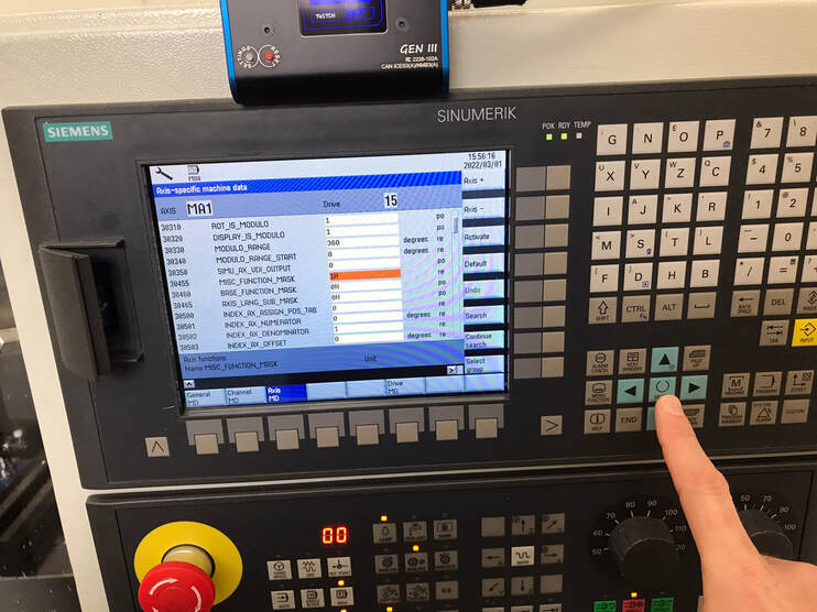
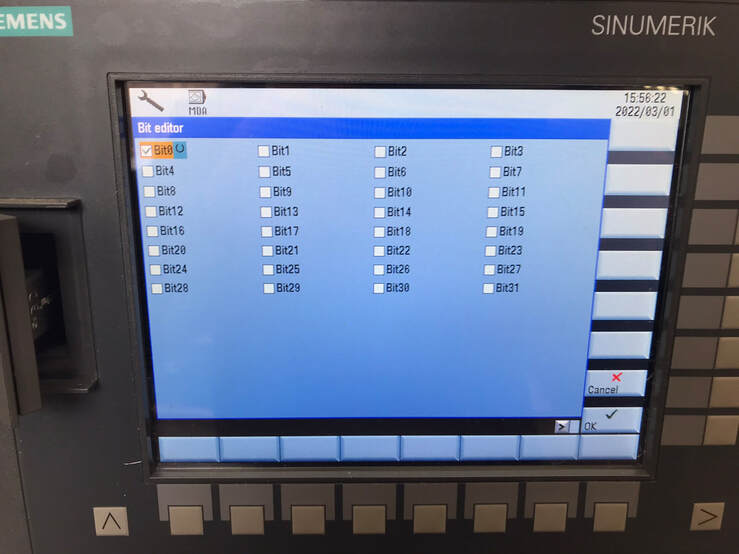
Axis Data Parameter MD 30455. enable bit 0 (zero) (when you have the 30455 setting highlighted, press the horseshoe select button (middle of the blue directional arrows) to open the bit editor screen, then put an 'x' in the bit zero box) to allow the control to accept commands outside of the modulo range (i.e. -10, +700), the effect is calculated internally. If you are at A0 and program A=370, the axis will move to 10 degrees without making a full revolution, however, if you are at 350 degrees and you command A370, the axis will continue "wrapping" around to 10 degrees, and this way the program can be written to continue wrapping around into the thousands of degrees. This will become more important as we unlock 4 axis simultaneous machining settings in the post and control (work in progress).
SHIFT + SYSTEM > set password > (enter password "sunrise") > MACH. DATA > EXPERT LIST > AXIS MD > (now use the "axis +" button to scroll to MA1 axis) > (scroll down to 30455 and when it is highlighted, press the horseshoe select button seen below)
spindleScrewWarmupCallv2.mpf
spindleScrewWarmupSubv2.spf
There is a .zip file in the downloads that contains two programs. a "CALL" and "SUB" program. unzip both and place them BOTH in the NC program folder in the control.
To run the warmup program, open the "CALL" program and change the settings to match your machine/ preferences.
There are 3 modes to select from:
In addition, you can choose whether you want to warm up the spindle only, spindle and XY, or spindle +XYZ. You can set your XY travels, as well as where you want to do the Z plunge (in X and Y MCS coordinates) and what Z- you want to plunge to. Make sure the area you want to plunge to is clear.
When you have made your selections, press execute to run the program.
spindleScrewWarmupSubv2.spf
There is a .zip file in the downloads that contains two programs. a "CALL" and "SUB" program. unzip both and place them BOTH in the NC program folder in the control.
To run the warmup program, open the "CALL" program and change the settings to match your machine/ preferences.
There are 3 modes to select from:
- Daily- Use this when the spindle hasn't run for up to 3 days.
- 72Hr+- Use this when the spindle has been idle for between 3 days and 2 weeks.
- 2 weeks+- Use this when the spindle has not run for 2 weeks or more.
In addition, you can choose whether you want to warm up the spindle only, spindle and XY, or spindle +XYZ. You can set your XY travels, as well as where you want to do the Z plunge (in X and Y MCS coordinates) and what Z- you want to plunge to. Make sure the area you want to plunge to is clear.
When you have made your selections, press execute to run the program.
BRK.MPF
The brk.mpf program needs to be pasted into the NC program area of the control.
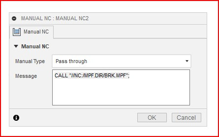
Then, using manual NC- pass through in fusion 360, you can simply insert this call after the operation you want the tool that was used to be checked for breakage:
The brk.mpf program needs to be pasted into the NC program area of the control.
Then, using manual NC- pass through in fusion 360, you can simply insert this call after the operation you want the tool that was used to be checked for breakage:
Code Editor
The code will then automatically check the length of the tool (using the TTC-200) in the spindle and error out if it has changed beyond the preset tolerance.
measureCurrentToolLength.mpf
Load a tool in the spindle (and make sure the correct D number is enabled), then call this program to measure its length. Note that there needs to be a rough estimated length for the tool in the offset table.
Load a tool in the spindle (and make sure the correct D number is enabled), then call this program to measure its length. Note that there needs to be a rough estimated length for the tool in the offset table.
Prices in US Dollars

