- Store
- >
- Pick and Place (PnP)
- >
- Parametric pick and place (PnP) machine design with BOM!
Parametric pick and place (PnP) machine design with BOM!
SKU:
$0.00
Unavailable
per item
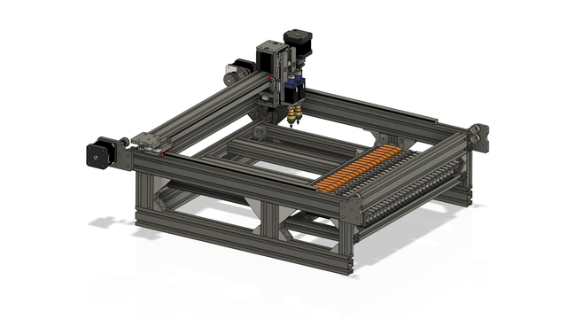
Fully parametric reference machine design. You can open the parameters table in the design and adjust any of the "USER" variables and the machine will rebuild around your desired dimensions.
Sold Out
Don't use Fusion360 or have no idea what that even means ?!?! Scroll down to see how this CAD model is still useful to you!
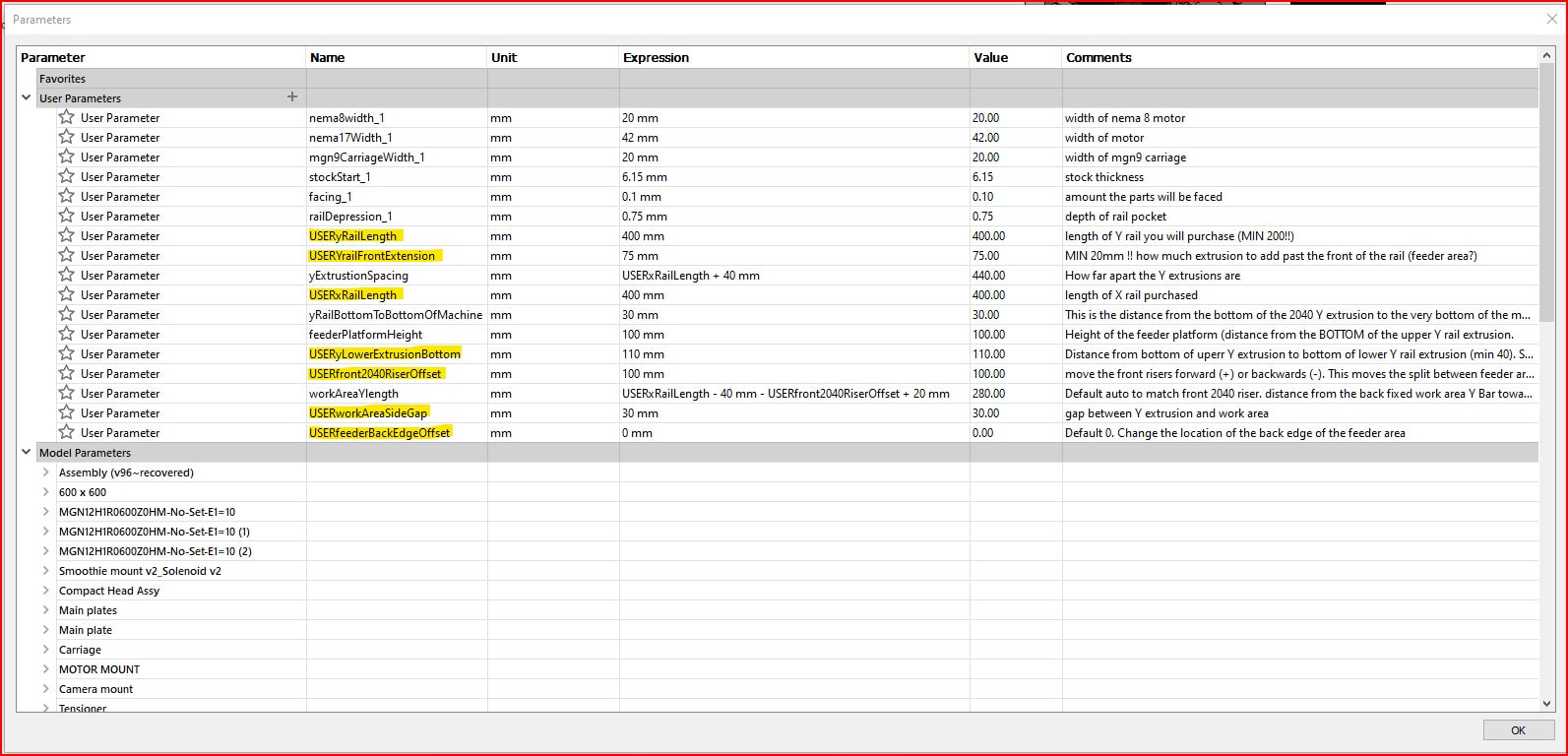
I am building a new PnP for myself, and while I knew what size I wanted it, I decided to take the time to make it fully parametric (Fusion360 required to utilize parameter, you can download and use it for free as a hobbyist or start-up) (model is built using a table of modifiable variables that can be changed) for other people to use. The variables that start in USER are the ones you can play with.
The main variables are the X and Y rail lengths. Simply enter the desired length of rails you wish to purchase and the model will rebuild around them!
The main variables are the X and Y rail lengths. Simply enter the desired length of rails you wish to purchase and the model will rebuild around them!
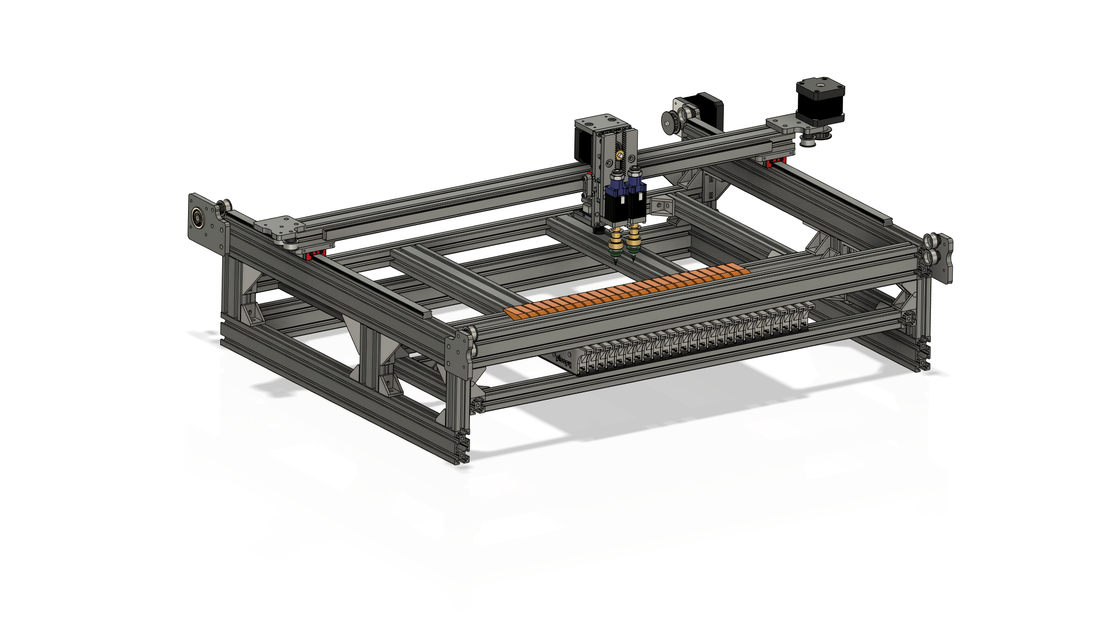
The default is 400mm rails, but here is what happens if you adjust USERxRailLength to 600mm:
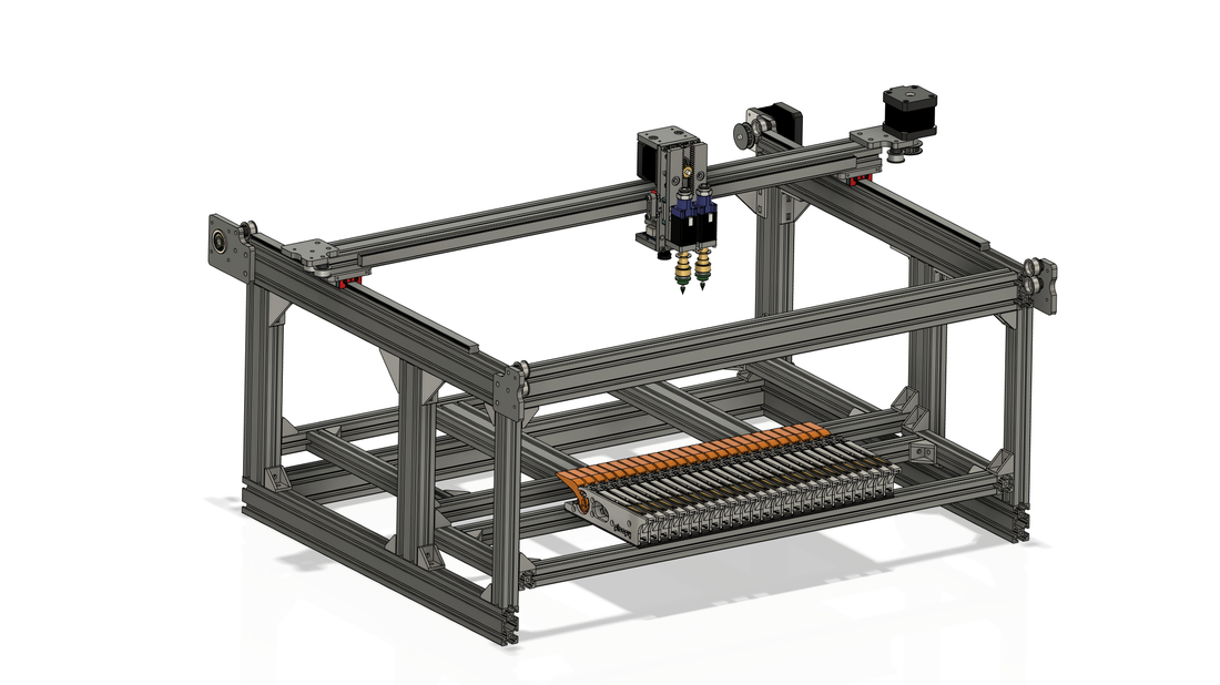
And if you adjust USERyLowerExtrusionBottom to 250mm:
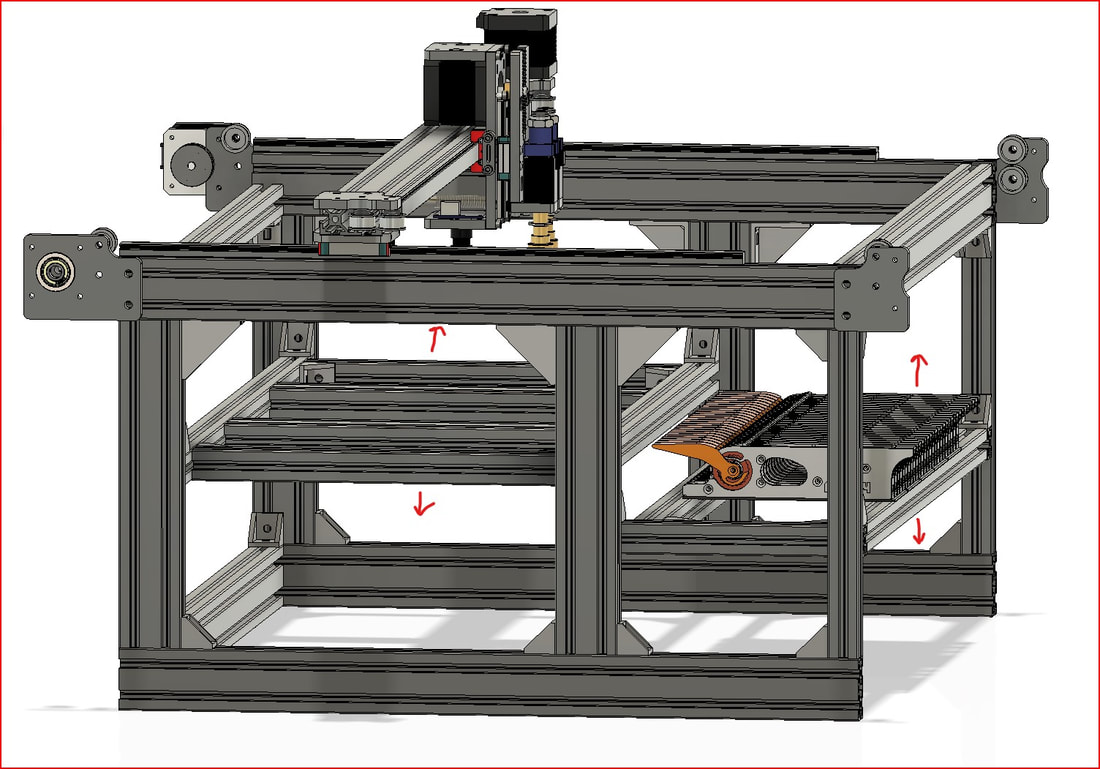
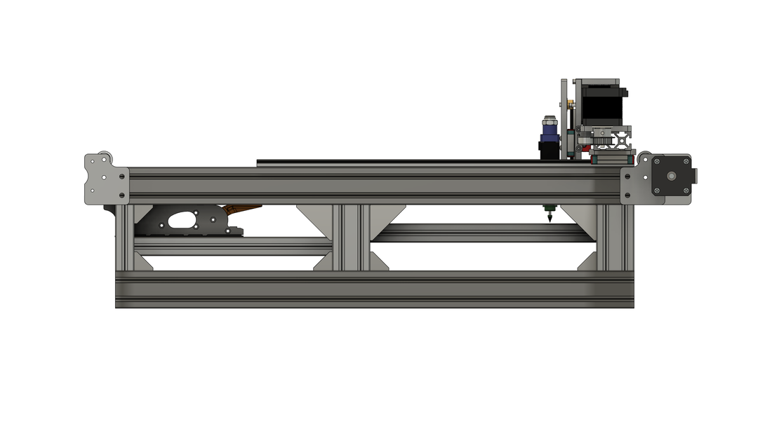
The design features a "work area" and a "feeder area" (Ploopyco feeders shown in feeder area), which are two independent inner frames. You can move each frame up and down to achieve your desired height relative to the head. In the model these joints are present so you can drag each frame up and down to visualize the effect:
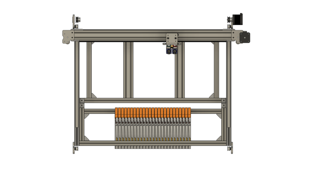
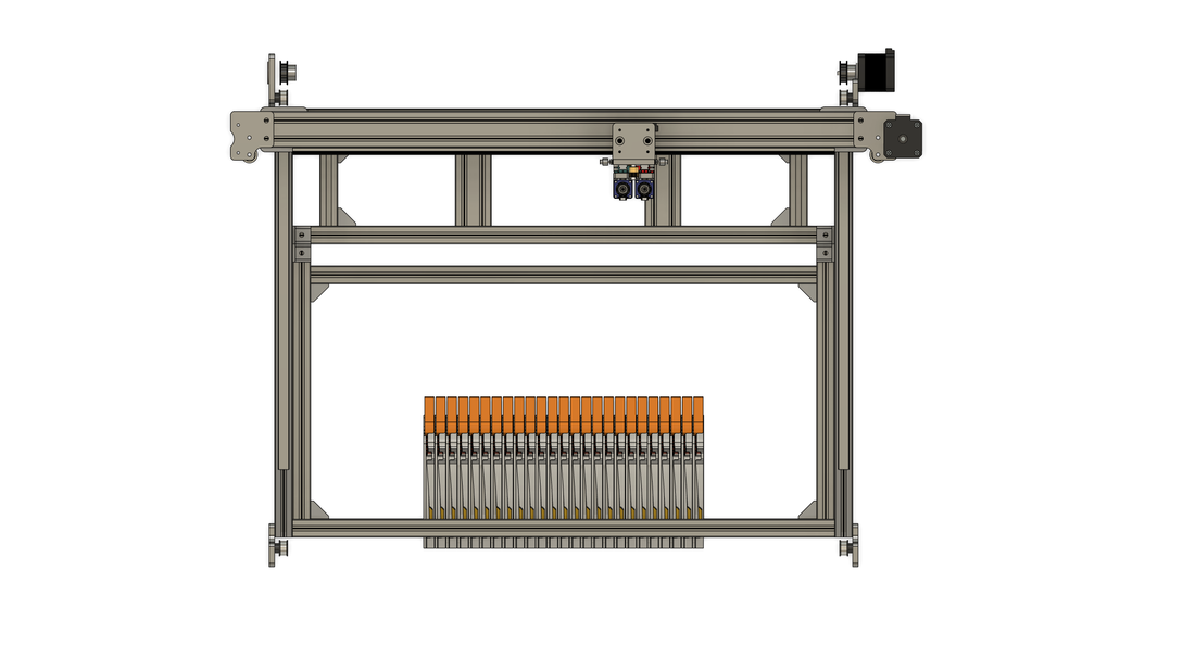
The split (or ratio) between the work area and feeder area is determined by the USERfront2040RiserOffset variable. The image below on the left shows it set to the default of 100mm (smaller feeder area), and the right set to 250mm (smaller work area):
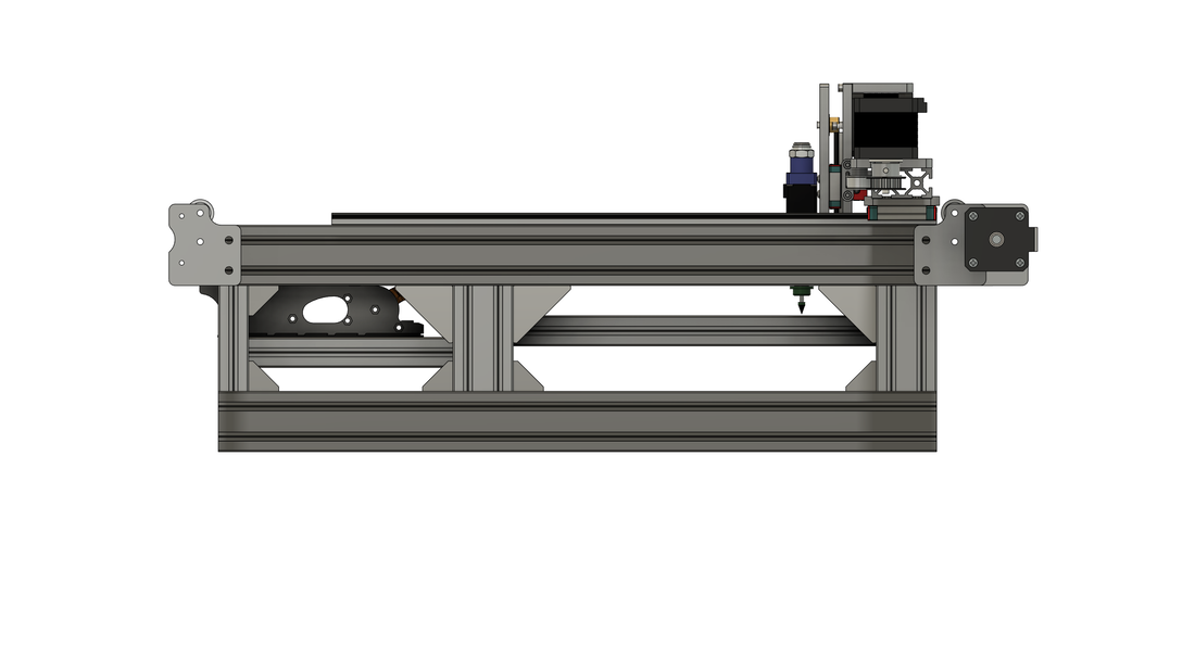
Another important variable is USERyRailFrontExtension. This basically determines how far the Y rail extrusion carries on past the front end of the Y rail (minimum 20mm). This also has an effect on the feeder area size. Below left shows the variable set to the default of 75mm, and the right set to 150mm:
The model operates just like it will in real life, all joints and joint limits rebuild based on the parameter table, even the head moves up and down so you can see where you can pick and place parts from.
Y AXIS DRIVE CONFIGURATIONS
There are a couple of ways to drive the Y rails (both are supported by the BTI plate kits). Both of these methods are in the model, just turn on the one you want to see and turn off the ones you don't:
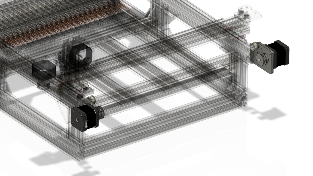
DUAL Y MOTORS. You can mount a NEMA17 motor on both Y rail motor plates. You can get smoothie boards like the SKR 1.4 that have plugs for dual Z motors (for many types of 3D printers) that you can use to drive both Y motors from.
DUAL Y MOTORS. You can mount a NEMA17 motor on both Y rail motor plates. You can get smoothie boards like the SKR 1.4 that have plugs for dual Z motors (for many types of 3D printers) that you can use to drive both Y motors from.
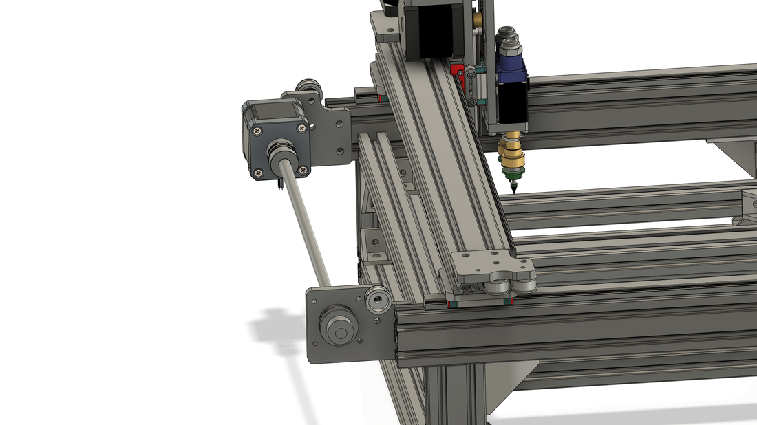
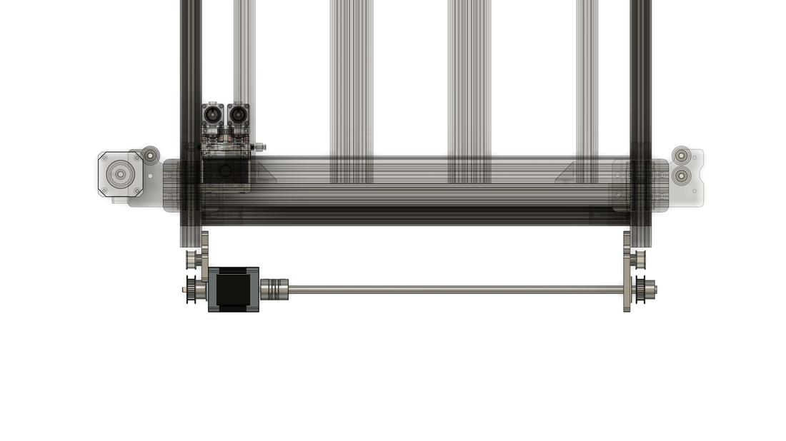
SINGLE Y MOTOR AND DRIVESHAFT CONFIG. There are two methods of accomplishing this:
A: This method uses a single dual-shaft NEMA17 stepper and a 5mm to 8mm coupling to an 8mm driveshaft to drive the 36T pulley (with 8mm bore!!) on the other Y rail. To accomplish this, you need to move the motor plate to the inside of the Y rail 2040 extrusion, so you need to adjust the USERupper2040RearStickOut parameter to 20mm (bare minimum 15mm). This will cause the extrusions to protrude from the frame and provide space to attach the Y motor mounts:
A: This method uses a single dual-shaft NEMA17 stepper and a 5mm to 8mm coupling to an 8mm driveshaft to drive the 36T pulley (with 8mm bore!!) on the other Y rail. To accomplish this, you need to move the motor plate to the inside of the Y rail 2040 extrusion, so you need to adjust the USERupper2040RearStickOut parameter to 20mm (bare minimum 15mm). This will cause the extrusions to protrude from the frame and provide space to attach the Y motor mounts:
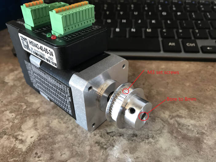
B: This method uses a single shaft motor (normal NEMA17, or closed-loop NEMA17 as seen below) and a modified 36T pulley to allow it to mount on the end of a single shaft NEMA17 motor (5mm shaft) and also couple to an 8mm driveshaft. You do not need to have the extrusions protrude like in method A as the plates need to be installed on the outside of the Y rail 2040 extrusions. We will probably put a couple of M3 set screws in the toothed area of the pulley to grab the stepper shaft. We have more than enough teeth in contact to still exceed the min spec of 6 teeth in engagement as per Gates. Then the other part of the pulley we will bore out to 8mm. Once we test this we will probably sell them on our site in the short term and see if robotdigg will make some and put them on their site (with a better design than this):
DOWNLOAD OR VIEW DESIGN
|
Fusion file is a little bit broken at the moment! Working on it.... 2021-10-22
|
Bill of Materials (BOM)
This is a work in progress so please let me know if there are any issues or something you would like to see added!
Don't use Fusion360??
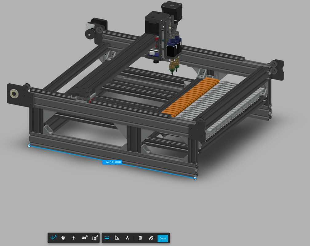
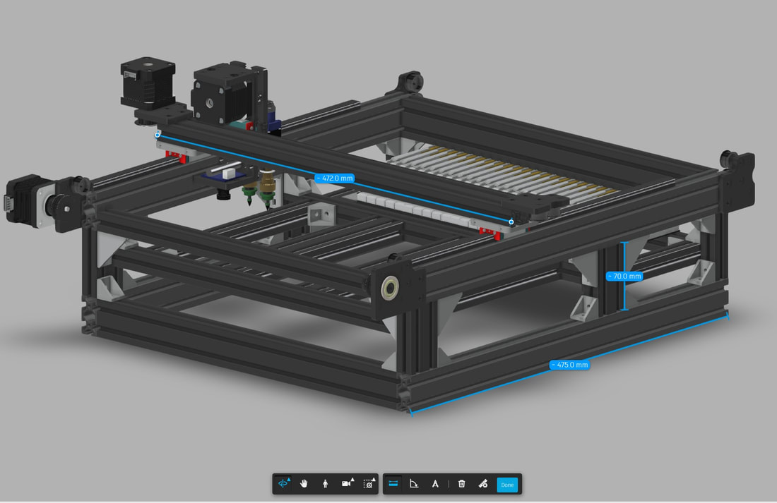
The link above will open the model in A360, which is an online viewer for Fusion360 models. You will not be able to modify the parameters, but if you are happy with the default of 400mm rails in X and Y, then you can measure all the extusions in A360 to build your cut list. You can also figure out how long to cut them if you used different length rails and wanted a different size feeder area etc:
Prices in US Dollars

