ota has arrived
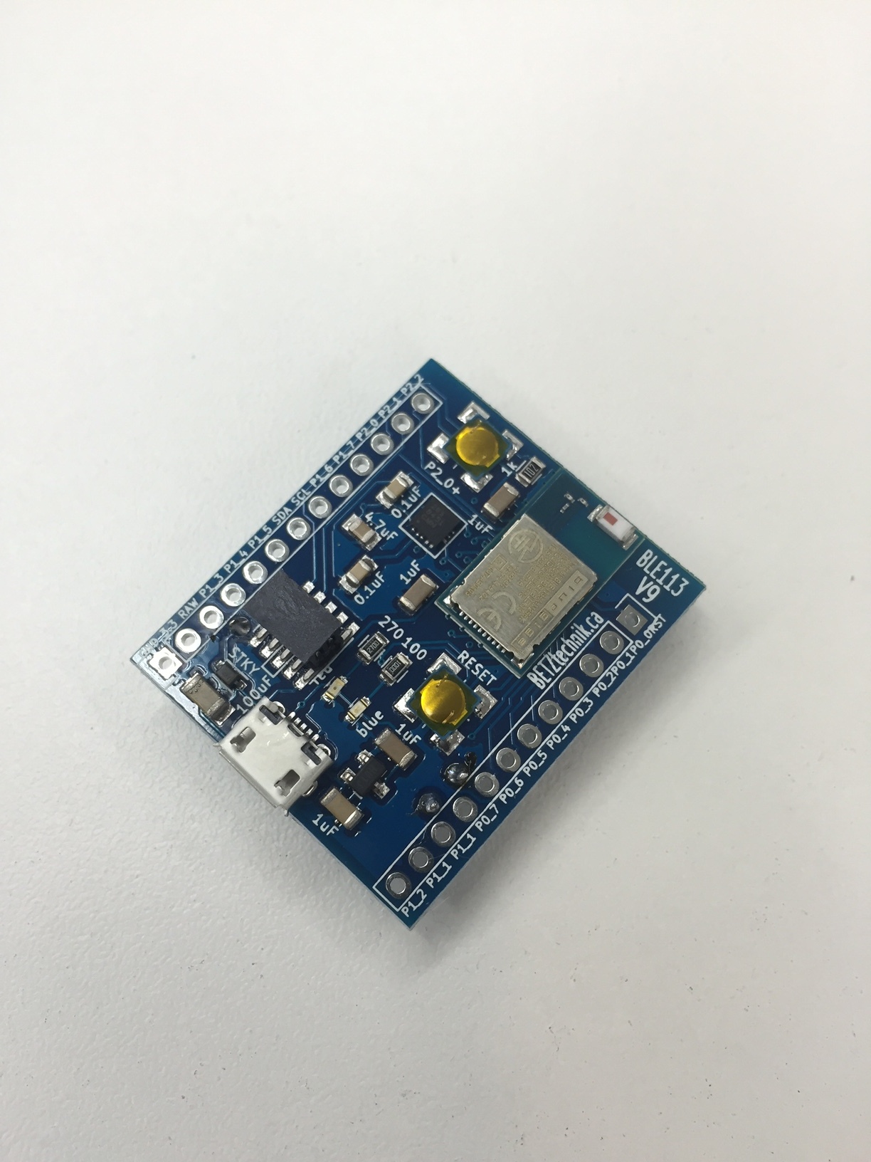
NEW: V9 now in stock! Now featuring more robust design, true 16v tolerance and added the same accelerometer as found on the Dev Kit (The ACC hasn't been tested yet so it isn't a feature we guarantee! If you get it working before we do we will refund you 1 board cost for sharing the code we can put on this page)
OTA (Over The Air) firmware update capable!
The 10 pin male 2.54mm pitch programming header for the CC Debugger is on the board, in the picture it has a plastic cap on it for pick and place assembly.
Note the BGM113 version requires a Segger programmer. We will post more details once we get it all working, it will not use the 10 pin CC debugger header, it will use the pins along the side of the board.
All you need to be able to flash new firmware over the air is a BLE dongle such as the BLED112 or my BLE112 breakout board connected to your computer via USB cable. See our blog for a overview of the OTA process! (Note the blog is a little out of date but still gives a rough overview)
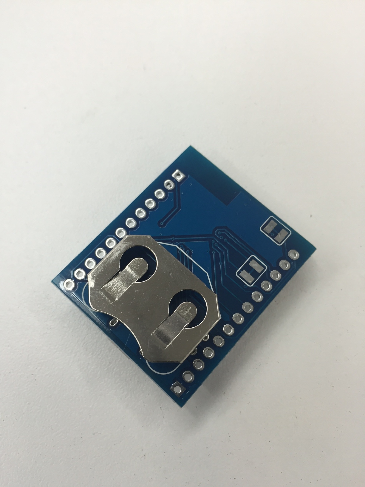
Our breakout board is equipped with a through hole coin cell battery holder (20mm, CR2032) on the backside. It breaks out all of the BLE113 pins and includes all required caps for the BLE113, 3.3v regulator and the battery. The board has LEDs on P1_0 and P1_1 (the 20mA drivers). No redundant pins for a more compact design. The newest design now includes a micro USB connector to enable easy powering of the device, just plug and play (The BLE113 has no actual USB functionality, for that you will need the BLE112)!
I have modified the BGDemo firmware from Bluegiga to run on the BLE113 boards WITHOUT OTA (though the non-OTA boards are now obsolete). The red LED will illuminate after the module has completed boot-up, not just when the board has power. When the board has established a connection the blue LED will illuminate and the red LED will extinguish. The board will also retain all of the other functionalities of the BGDemo Firmware. See below to download this firmware!
OTA equipped boards will ship with the OTA example hardware and they will be flashed over the air at least once to ensure the hardware works.
The board may be powered in the following ways:
3.3v direct: Supply the board with 3.3v on the 3.3v pin, no need for the voltage regulator or the coin cell battery to be utilized or even mounted. Switch set to REG to avoid conflict with battery.
4- 20v raw input: Supply 4- 20v to the RAW pin and utilize the 3.3v regulator to power the unit. No need to mount the coin cell holder. Switch set to REG.
Coin cell operation: Mount the coin cell battery holder on the back side and use the coin cell to power the board directly, a truly wireless stand alone application. No need to mount the 3.3v reg. Switch set to BAT.
USB: Just plug in a USB cable with the switch set to REG!
CC Debugger: The board is designed to be powered by the CC Debugger, just make sure the coin cell battery is removed first!
You will need a CC Debugger to program this board, you can add one to your cart here!
Due to increased dangerous goods restrictions, the boards will no longer ship with the lithium ion coin cell batteries. They are easily procurable however at your local hardware or electronics store (even with shipping charges it is still probably cheaper to have them overnight shipped from Digikey, click here)!!
Tech tips:
-The LEDs are not power indicators! They will not turn on until you have programmed them to. When you are using OTA, the blue light will illuminate while the external flash memory is being accessed. If you want firmware that will not be OTA capable but enables the RED LED after MCU boot (not just power up) and the BLUE LED after it makes a successful connection then try the firmware at the bottom of the page.
- If you connect the CC Debugger to the board and the CC Debugger light is RED, simply try the reset button on the Debugger before troubleshooting.
- Ensure you do not power the board from two sources simultaneously, this may damage the board.
- Make sure your firmware is low current compatible, if you run standard firmware with rapid advertising intervals and/ or no sleep enabled you will be lucky to get 8 hours out of the battery. When properly configured this board should last over 1 year on a coin cell battery.
- Make sure you only use the BG SW update tool in the SDK to upload firmware, if you use smartRF studio you will lose your license key!
IF YOU SELECT THE BGM113 BOARDS, THE SILK LABELS WILL NOT MATCH. PLEASE SEE THE BGM113 SCHEMATIC BELOW TO DETERMINE PIN NAMES.
OTA (Over The Air) firmware update capable!
The 10 pin male 2.54mm pitch programming header for the CC Debugger is on the board, in the picture it has a plastic cap on it for pick and place assembly.
Note the BGM113 version requires a Segger programmer. We will post more details once we get it all working, it will not use the 10 pin CC debugger header, it will use the pins along the side of the board.
All you need to be able to flash new firmware over the air is a BLE dongle such as the BLED112 or my BLE112 breakout board connected to your computer via USB cable. See our blog for a overview of the OTA process! (Note the blog is a little out of date but still gives a rough overview)
Our breakout board is equipped with a through hole coin cell battery holder (20mm, CR2032) on the backside. It breaks out all of the BLE113 pins and includes all required caps for the BLE113, 3.3v regulator and the battery. The board has LEDs on P1_0 and P1_1 (the 20mA drivers). No redundant pins for a more compact design. The newest design now includes a micro USB connector to enable easy powering of the device, just plug and play (The BLE113 has no actual USB functionality, for that you will need the BLE112)!
I have modified the BGDemo firmware from Bluegiga to run on the BLE113 boards WITHOUT OTA (though the non-OTA boards are now obsolete). The red LED will illuminate after the module has completed boot-up, not just when the board has power. When the board has established a connection the blue LED will illuminate and the red LED will extinguish. The board will also retain all of the other functionalities of the BGDemo Firmware. See below to download this firmware!
OTA equipped boards will ship with the OTA example hardware and they will be flashed over the air at least once to ensure the hardware works.
The board may be powered in the following ways:
3.3v direct: Supply the board with 3.3v on the 3.3v pin, no need for the voltage regulator or the coin cell battery to be utilized or even mounted. Switch set to REG to avoid conflict with battery.
4- 20v raw input: Supply 4- 20v to the RAW pin and utilize the 3.3v regulator to power the unit. No need to mount the coin cell holder. Switch set to REG.
Coin cell operation: Mount the coin cell battery holder on the back side and use the coin cell to power the board directly, a truly wireless stand alone application. No need to mount the 3.3v reg. Switch set to BAT.
USB: Just plug in a USB cable with the switch set to REG!
CC Debugger: The board is designed to be powered by the CC Debugger, just make sure the coin cell battery is removed first!
You will need a CC Debugger to program this board, you can add one to your cart here!
Due to increased dangerous goods restrictions, the boards will no longer ship with the lithium ion coin cell batteries. They are easily procurable however at your local hardware or electronics store (even with shipping charges it is still probably cheaper to have them overnight shipped from Digikey, click here)!!
Tech tips:
-The LEDs are not power indicators! They will not turn on until you have programmed them to. When you are using OTA, the blue light will illuminate while the external flash memory is being accessed. If you want firmware that will not be OTA capable but enables the RED LED after MCU boot (not just power up) and the BLUE LED after it makes a successful connection then try the firmware at the bottom of the page.
- If you connect the CC Debugger to the board and the CC Debugger light is RED, simply try the reset button on the Debugger before troubleshooting.
- Ensure you do not power the board from two sources simultaneously, this may damage the board.
- Make sure your firmware is low current compatible, if you run standard firmware with rapid advertising intervals and/ or no sleep enabled you will be lucky to get 8 hours out of the battery. When properly configured this board should last over 1 year on a coin cell battery.
- Make sure you only use the BG SW update tool in the SDK to upload firmware, if you use smartRF studio you will lose your license key!
IF YOU SELECT THE BGM113 BOARDS, THE SILK LABELS WILL NOT MATCH. PLEASE SEE THE BGM113 SCHEMATIC BELOW TO DETERMINE PIN NAMES.
|
| ||||||||||